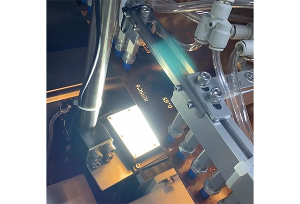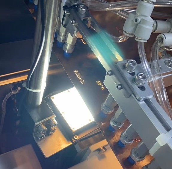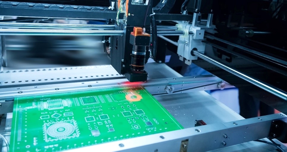
W części kontroli jakości tego projektu napięcie mierzy się za pomocą dwóch sond, które wbijają odpowiednio oba końce łączy lutowych, aby ocenić, czy łącze lutowe na płytce PCB są w dobrym kontakcie i wyeliminować problematyczne produkty.
Udostępnij
1) tło projektu:
opis wymogu:
po pierwsze, płyta PCB jest fotografowana przez górną kamerę, a współrzędne łączy lutowych, które należy zmierzyć, są podane do grubego pozycjonowania. Następnie dwa manipulatory odpowiednio przenoszą sondę do odpowiednich współrzędnych, aby sfotografować
punkty bolesne i problemy:
1.w przypadku tradycyjnego systemu koszty całego zestawu aparatu fotograficznego, obiektywu, źródła światła, sterownika źródła światła i innych urządzeń są wyższe.
2.tradycyjny system ma skomplikowany proces, wysokie wymagania dotyczące personelu do debugowania w miejscu i wysokie koszty pracy.
3.tradycyjne rozwiązanie ma długi okres debugowania i nie może być uruchomione szybko.
2) architektura rozwiązania:
schemat erekcji:

proces debugowania:
1. manipulator nosi kartę kalibracyjną i utrzymuje taką samą wysokość co płyta PCB. robi zdjęcia na aparaturze, buduje proces za pomocą VM, otrzymuje współrzędne fizyczne manipulatoru za pośrednictwem protokołu komunikacji TCP i wykonuje automatyczną kalibrację w dziewię
2. ramię robota posiada inteligentną kamerę do fotografowania tablicy kalibracyjnej, wykonywania stemplowania punktów i generowania plików kalibracyjnych poprzez obrazy i współrzędne fizyczne dziewięciu punktów
3. pozycja płyty PCB jest przesyłana do ramienia robota, a ramię robota przenosi inteligentną kamerę do odpowiedniej pozycji do fotografowania spoju lutowego
4. inteligentna kamera wykorzystuje wyszukiwanie miejscowe do wpisania każdej pozycji stopu lutowego w kolejności, kalibrowania współrzędnych i konwersji w celu osiągnięcia sortowania
5.Po wykonaniu różnicy między pozycją kalibracyjną zdjęcia inteligentnego aparatu a pozycją zdjęcia produkcyjnego dodaj wartość konwersji kalibracji spoin lutowych, aby uzyskać rzeczywistą pozycję każdego spoinu lutowego
3) zalety programu:
1. użyć górnej kamery do bezpośredniego fotografowania współrzędnych manipulatorów po obu stronach, a oba manipulatory bezpośrednio osiągają punkt docelowy po zrobieniu zdjęć poprzez kalibrację i transformację, i nie ma potrzeby kolejno do niego wchodzić, co znacznie oszczędza czas ruchu manipula
2. poprzez zmniejszenie prostokątnego pudełka złącza lutowego poszukiwania i umieszczenie każdego złącza lutowego indywidualnie, może być dobrze umieszczony w miejscu złącza lutowego. klienci wymagają dokładności 0,1 mm, a bieżąca dokładność osiąga 0,05 mm, aby
3. ten projekt jest klasyczny inteligentny aparat fotograficzny i aparat fotograficzny przemysłowy razem do wykorzystania projektu, rzeczywisty projekt może być wybrany zgodnie z rzeczywistymi potrzebami odpowiedniego typu aparatu fotograficznego, a nawet oba razem dostosować do środowiska klienta, aby osiągnąć odpowiedni efekt.
4. pierwotny plan klienta polegał na przesłaniu współrzędnych do odpowiedniej pozycji górnej kamery po zrobieniu pierwszego zdjęcia i przesłaniu współrzędnych do drugiego zdjęcia po zrobieniu drugiego zdjęcia. obecny plan wymaga tylko zrobienia jednego zdjęcia i wywołania różnych plików kalibracyjnych


